Abstract
This report presents a summary of my Coop training report and the task that I completed in 28 weeks of the training. The report has three sections based on different areas of the study. The first Unit covers the work I completed at Baxter Company Limited under the heat transfer system. The unit operates with three distinct components. It offers consultation services on heat transfer equipment.
The report focuses on heat transfer machines, which include heat exchangers, boiler, and distiller machines. It shows types of equipment, design specifications, and possible equipment failures. Finally, the report covers study cases and consulting assignments I undertook during the Coop training.
Acknowledgments
My thanks and prayers go to Allah for His guidance and protection in my life. I also acknowledge my parents for their support and help and taking care of me throughout my life. They enabled me to achieve all that I have now.
I also thank King Fahd University of Petroleum and Minerals and Mechanical Engineering Department for the wonderful opportunity and support they accorded me during this assignment, which helped me to relate theory and field practices.
Baxter Company Limited also played a significant role by giving a wonderful chance to work alongside its team of qualified and experienced engineers. They provided me with the necessary assistance I required to complete my project successfully. Specifically, I express my profound gratitude to Dr. Forqan for his thorough guidance, reviews, and support at Baxter.
Lastly, I would like to state that the Co-op training session was a magnificent opportunity that exposed me to a real work situation, which will shape my future and career.
Introduction
My attachment was with Baxter Company Limited (BCL). BCL manufactures pharmaceutical products. It also engages in water treatment by eliminating bacteria to provide water for medical solutions and peritoneal dialysis. Rainwater has many impurities from the atmosphere, such as CO2 and other elements, which dissolve in water and could be dangerous to human health. Rainwater also picks certain dangerous chemicals and metals like lead, pesticides, and fertilizers among other dangerous substances.
Likewise, water in reservoirs also has several microorganisms and natural minerals. Tap water and other sources of water for human consumption are treated to remove these impurities and make water safe for human consumption. All countries have regulations that ensure that water for human consumption meets specific quality requirements in terms of mineral and substance contents. While tap water is suitable for human use, they are not appropriate for use in medical solutions and peritoneal dialysis. Water for manufacturing pharmaceutical solutions must be particularly pure. The need for pure water for pharmaceutical solutions and peritoneal dialysis was the main reason that led to the establishment of BCL. BCL provides quality pure water for pharmaceutical purposes. The report will show my Co-op progress while at the company.
Pharmaceutical water must meet safety standards by being free from any form of contamination. The Association for the Advancement of Medical Instrumentation ensures the standard of water for pharmaceutical solutions meets the required specifications.
Heat transfer mechanisms have several applications in mechanical engineering. However, only three devices have wider applications. They include a distiller machine, heat exchanger, and boiler. Hence, the Co-op training report will focus on these three equipment and possible technical challenges with these machines.
The Host Company and Co-op Assignment
An Overview of BCL
Founded in the fall of 2009, Baxter Company Limited (BCL) is a joint business between the Olayan Group and Baxter Healthcare Corporation. BCL was the 58th factory of Baxter and the first one in the Middle East region. The company produces intravenous medical solutions and peritoneal dialysis solutions for patients with renal conditions. The relationship between Olayan and Baxter dates back to 30 years ago when it worked with Arabian Healthcare Supply Company (AHSC) to offer products from Baxter. AHSC is a fully owned subsidiary of Olayan Group. Baxter Healthcare develops, manufactures, and promotes medical products for people with immune disorders, kidney disease, hemophilia, infectious diseases, trauma, and other chronic and acute diseases. BCL leverages its knowledge of medical equipment, biotechnology, and pharmaceuticals to develop advanced medical solutions. Some of these medical solutions include commercially developed intravenous solutions, kidney dialysis machines, concentrated clotting factors for hemophilia, and pandemic flu vaccine developed from cell cultures.
Co-op Plan and Activities
The KFUPM regulations require an intern to complete 28 weeks of training. This Co-op plan was organized by the supervisor and mentor to meet BCL requirements and comply with training periods as follow:
During the Co-op session, the plan involved working alongside qualified, experienced, and highly skilled professional engineers to accomplish different tasks. The process involved learning and knowledge acquisition. These professionals were responsible for induction into the three main gadgets used in the unit, which included heat exchanger, boiler, and distiller machine. The process involved understanding the functions and operations of these machines and then using the acquired knowledge in real situations and case studies to solve problems.
Heat Transfer Equipment
Heat transfer is a critical role in most engineering processes, particularly where there are several functions, devices, and systems. Heat transfer helps in transferring heat or thermal energy from one system to another. This section discusses three major heat transfer devices used during the Co-op training at Baxter.
Distiller machine
Stage 1
Water treatment chain
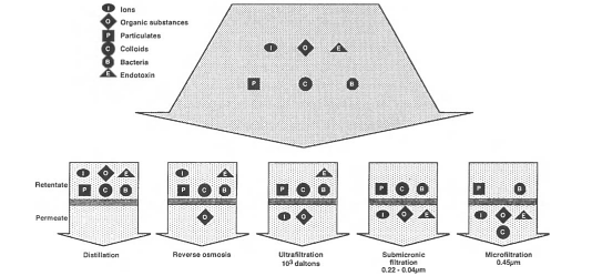
BCL determines water contamination by applying three distinct classifications, which include dissolved substances, microorganisms, and particles. Water from external sources, which is pumped into the company’s reservoirs, contains different particles like sand, clay, and iron. These elements cause water turbidity (make water appear muddy). Substances in water are both living and non-living impurities. There are several processes involved in water purification for pharmaceutical purposes. These processes involve pre-treatment and a two-stage process that consists of reverse osmosis treatment.
Pre-treatment process
Several methods are used to produce ultrapure water as demonstrated in figure 1 below (Jacobs 232). Studies have indicated that a distillation procedure results in high-quality water relative to other procedures. However, BCL does not use distillation because the process requires huge amount of energy, but produces small volumes of water.
Treatment system
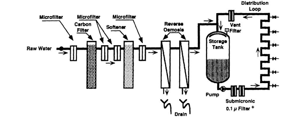
BCL acknowledges that it is not possible to get ultra pure water from a single process. As a result, it uses several devices with different procedures to treat water. The company uses devices, which can produce the quality of water required for medical purposes. Figure 2 shows the system used at the company’s plant.
The system has a valve to prevent any possible backflow of water. The valve is at the joint that connects the system and the incoming pump from external sources of water. Another booster pump controls the valve gadget and helps the pump to build the minimum needed pressure from the feed line.
Water filtering
BCL pumps water from external suppliers into its storage tanks. After this, it pumps water into a treatment chamber. The first process involves filtering impurities. The system has sand filters, which consist of 25 to 31 inches of sand grains. In order to prevent the growth of microorganisms trapped in the sand particles, BCL removes the top layer regularly. The system also has activated carbon filters to remove dissolved organic elements and chlorine chloramines from the water. Carbon is a part of an adsorptive device and a pre-treatment clearing system. Carbon has great surface area to mass ratio, which is suitable as a component of adsorptive substances. This property allows carbon to absorb chlorine and chloramines dissolved in the water.
Several factors influence the adsorption capacity of carbon. These include quantity and quality of the carbon used, chlorine and chloramines present in the water, and the volume of the incoming water. The company chooses its carbon filters based on the degree of contamination of the water and the source of the water. It also conducts regular backwashing of carbon filters in order to remove accumulated organic elements. This process also restores adsorptive quality by protecting media components from channeling cases. Any failure to maintain carbon adsorptive quality results in passage of chemicals to the next stage.
On this note, engineers should monitor and change carbon and sand filters regularly. While sand filters can be regenerated well, carbon filters lack this quality. Hence, carbon filters are disposable. BCL has a team of technicians who monitor and maintain filters regularly. They also replace old filters in order to maintain the best performing standards.
Water softening
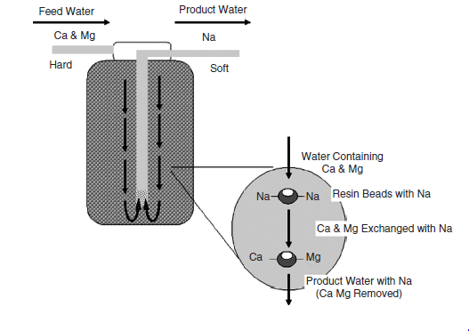
The next stage after water filtration involves water softening. Water from external sources is not soft. It is important to transfer only soft water to the reverse osmosis section to prevent any possible damage to the system. In most cases, water that proceeds to the reserve osmosis chamber has calcium and magnesium. Water softeners lower the level of divalent ion charge and shield the membrane of the system from scaling and building up. Ion exchangers are main substances used in water softeners. They are in cationic forms and exchange two Na+ ions for Ca++ and Mg++ and other cation ions like manganese and iron. The volume of soft water produced depends on the volume of resin.
A function of the total hardness of the incoming water, flow outcome, and consumption ratio, resin quality, and the rate of regeneration cycles are used to determine the effectiveness of a softener. After a complete exchange of Na+ ions, the resin becomes obsolete and must be restored to avoid problems of hard water syndrome. BCL ensures that all processes involved with softeners are done on-site by using a brine sodium chloride solution by altering the ion exchange process. The process leads to the restoration of Na+ ions on the resin by altering the divalent fixed ions. The regeneration of used resins is performed on a large-scale basis outside the site. Calcium from the used resin goes to a non-desired state referred to as a hard water syndrome. At BCL, engineers limit hard water syndrome by conducting daily monitoring and maintenance of the system. Just like in the filtering process, the water softening process may also be affected by the growth of microorganisms. However, engineers use backwashing to avoid the growth of microorganisms in the water softening chamber. In addition, they also conduct regular sanitization in which the softener is flushed with extremely concentrated sodium hypochlorite solution to inhibit the growth of microorganisms. Figure 3 shows the water softener and its functioning processes.
Stage 2
The second stage is the last stage in water purification procedures. Deionisation or reverse osmosis alongside sterilizer equipment may be applied to complete water purification in this stage. While any of the above methods are suitable for water purification, BCL applies both methods at different series in order to enhance the quality of the purified water. After the softening process, water goes through UV sterilizer, deionization, and RO equipment.
UV treatment
The UV sterilizer relies on the solar energy to function. Hence, it is outside the building. Normally, sunlight has spectra like gamma and ultraviolet (UV). UV is effective for eradicating bacteria in the water during purification. However, ultraviolet treatment may not be an effective method of eradicating bacteria in purified water because some species of bacteria may still be present even after the UV treatment. However, the effectiveness of UV treatment depends on the depth of water, the intensity of the sunlight, and the flow rate of water. These factors show that UV treatment should not be applied alone in water treatment. Water treatment firms must use UV alongside other treatment methods to enhance water purification and the effectiveness of the method.
Deionization process
After water sterilization processes, the next process involves deionization where water passes through a deionization device. Hoffmann notes that deionization process removes inorganic ions from the water (Hoffmann 117). This process also uses the principle of ion exchange applied in the water softening stage. Engineers apply two types of ion exchange resin, which are cationic and anionic. Cationic resins replace hydrogen ions with cations. Conversely, anionic resin swaps over hydroxyl ions for anions. The cationic and anionic resins are mixed in a mixed bed deioniser. This process results in formation of water as hydrogen and hydroxyl exchange their ions. The resistivity of the affluent water determines the efficiency of the deioniser. Procedures in mixed bed deioniser result in effluent water. Double bed deionisers, which have cationic and anionic resins in different sections, generate water of low quality relative to water obtained through mixed bed deionisers. It is imperative to ensure that resins from dialysis chambers do not mix with resins from non-medical places, particularly in commercial regeneration of deioniser resins. Likewise, chemicals for regenerating resins should not have toxic elements. It is also important to ensure that chemicals are rinsed well before deioniser can be used in water treatment.
Deionisation is the best method for water purification. As a result, the resistance of water to electric current should be used to determine the quality of water. Several factors influence the quality of deionized water. These include composition of the supplied water, resin tanks involved in the deionization process, an ion exchange.
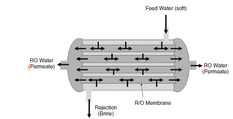
The reverse osmosis system
Reverse osmosis is affordable process relative to the methods above used in water purification. In addition, the method is also quite effective, particularly in disinfecting water with organic and inorganic elements (Jacobs 239). The method relies on the general principle of osmosis. Hence, osmosis process occurs across semi-permeable membranes because of differences in ionic concentration. Figure 4 below indicates the osmosis process in water purification.
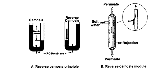
When one considers the left section of the figure above, any change in the hydraulic pressure of the concentrated side exceeds the osmotic pressure. Consequently, the flow of water will be reversed, and it will move from a highly concentrated side to a lowly concentrated side. This is the reserve osmosis process. It functions like a sieve that filters and separates solute above the membrane limit. Reverse osmosis inhibits the flow of incoming water and creates two fluxes.
Just like other processes of water purification, reverse osmosis also has many factors that affect its effectiveness. These may include the size of the membrane, pH, water temperature, characteristics of water components, levels of water contamination and concentration, and the production ratio. Characteristics of components in water consist of structures, surface area, and nature of the solution. Pre-treatment system effectiveness and the maintenance of the reverse osmosis membrane affect optimal performances and lifespan of reverse osmosis. The nature of the membrane may also influence its resistance to reverse osmosis, destructive effects of chemicals, disinfectants, or bacteria. The destructive nature of some bacteria affects cellulose acetate. Likewise, artificial membranes are more prone to caustic effect of some chemical species in water. Generally, thin compound membranes are highly effective and resistant to most corrosive agents.
BCL uses hydraulic pressure on the brine side in order to sift water against osmosis force through a semi-permeable casing (figure 5).
The company has technicians that watch regular performance of the reverse osmosis system. They observe the resistivity of both the produced water and the rejected one. The ratio of 0.85 to 0.95 in production or rejection shows that reverse osmosis system is performing optimally. However, any value that is below 0.80 shows that the membrane component requires a change. Water quality may also become low due to fouling or scaling that takes place on the membrane. The purity of the inflowing pre-treated water affects reverse osmosis. Companies should conduct scheduled flushing of the membrane in order to re-establish optimal performance of the reverse osmosis system. A preservation of the membrane property makes the reverse osmosis the most effective method of purifying water. The process eliminates bacteria based on the bacterial load in water and the proper tightness of the frame.
Therefore, the company can collect ultra-pure water from reverse osmosis and store it in a closed stainless steel storage tank. The tank has a concave design on all its ends while the internal surface has polish to inhibit the growth of bacteria. Pure water from the reverse osmosis system goes into the tank from the upper side of the reservoir. The water then moves to the concave chamber, which controls the flow of the water within the inner surface of the tank. This results in lasting linage of the wall. Ultrapure water can then be directed to distribution channels from the bottom of the tank. The tank works under-maintained water pressure.
Monitoring of water system
Baxter Company Limited has a proper system of monitoring water to ensure maximum operations. This section will cover some critical areas in the water monitoring system that require constant attention. Some of these areas include water softening chambers, carbon reservoirs, reverse osmosis section, deionized, filters, and other ancillary parts. In the water softener chamber, engineers observe water hardness at the end of each day. The water softener should be 1ppm. Measurements could indicate any deviation from the normal water pressure. When the pressure is under 10 Pascals, engineers start backflushing at the water softener junction. In every shift, they must observe the concentration of chlorine and chloramines in the carbon tank.
Engineers must monitor any change in water pressure, resistivity, and rejection ratio in order to ensure that the system works optimally at the reverse osmosis chamber. Moreover, regular monitoring of the system enhances the life of the semi-permeable membrane of the reverse osmosis system. In the deionization chamber, any changes in pressure should not go beyond 10 Pascals because any changes in pressure beyond this level could cause severe clogging in the reservoir. At the same time, engineers must also monitor filters frequently to identify any changes in pressures. The other ancillary parts like pump valves also require regular monitoring for any defects.
Heat Exchanger
A heat exchanger is a device that provides effective transfer of heat from one fluid to another, whether there is a physical separation between the fluids or not. Heat transfer entails a mechanical process that requires conduction and convection. In the convection transfer, heat flows from the hot fluid within the tube to inner parts of the same conductor. By conduction, heat moves through the conductor wall, whereas it moves from the outer surface of the conductor to the outside cold fluid.
Function and Types
Engineers achieve the following objectives when they use heat exchangers:
- A transfer of temperature from a hotter fluid to a colder fluid
- Heat transfer ensures a change of fluid from a liquid state to a vapor state at a constant temperature
All heat exchangers work by using the same transfer principle when transferring heat. However, the fluid, the design, layout, and the configuration of heat exchanger components may differ from one exchanger to another. The major types of heat exchangers are the following:
- Shell-and-tube heat exchangers
- Air-cooled heat exchangers
- Double-pipe heat exchangers
- Plate-and-frame heat exchangers
Heat Exchangers Components
Heat exchangers have several parts that ensure they function effectively as required. This section identifies the most common parts of heat exchangers in the plant (shell-and-tube) and shows various functions of different parts.
Shell-and-tube Heat Exchanger
- Shell
This is the container with the fluid
- Shell side nozzles
These are inlet and outlet ports of the heat exchanger
- Tube side channels and nozzles
These components control the movement of the tube side fluid into and out of the tubes.
- Tubes
Tube is the basic part of the shell, which has the surface for transferring heat
- Tube sheet
This is a round drilled metal plate, which makes the tube
- Girth flanges
Flange bolts the shell cover. Shell cover flanges are primarily designed for the shell-side environments
- Flat covers
Flat covers are designed for internal pass partitions of plates of the exchange
- Pass dividers
This component separates a channel or bonnet of the exchanger with two tube-side passes.
Tubes Failure and Maintenance
Tubes are fundamental parts of the heat exchanger. Its major purpose is heat transfer. These heavy duties may expose the heat exchanger to a number of failures. This section focuses on the most common types of the system failures, which can take place at the heat exchanger tubes. It also shows maintenance methods used on such failures.
Erosion Corrosion
Erosion corrosion is one major challenge that affects the heat exchanger system. Erosion corrosion is the removal of the metal surface because of high-speed friction caused by the flowing liquid. It causes severe attack, which can remove all the protective film on the surface of the tube and enhance the rate of corrosion. The rate of the liquid flow, density, and shape of the system affect the rate of erosion. In most cases, erosion-corrosion failure takes place when the liquid enters the tube or in parts that have U-shaped bends. These parts have extra shear tension that comes from the boundary layer and the movement of the liquid.
The best method for reducing erosion-corrosion involves the use of corrosion allowance. A corrosion allowance is an extra thick metal added to the tube in order to resist the friction and pressure from the load. The added thickness improves the metal thickness and reduces corrosion during heat transfer. In most cases, a process licenser or a mater engineer must determine and specify the corrosion allowance for any heat exchanger.
Fatigue Failure of Tubes
This type of failure occurs in the tube sheets. Tubes go through the tube sheets, and there are tube-to-tube joints. These points are prone to vibration, which causes the tube to be cold-worked. Extra strain weakens the tube and makes them prone to cracks and fatigue failure.
Fouling
During heat exchange processes that involve gases and liquid, a dirt coat slowly gathers in the heat transfer system. The dirt deposit could be coke, boiler scale, rust, silt, or any possible materials capable of forming dirt within the heat transfer system. The outcome of these deposits on the system is referred to as fouling. Fouling increases the heat resistance of the system. Technically, it is difficult for engineers to predict components of dirt deposits or the rate of fouling. Hence, regular cleaning of the heat exchanger guarantees optimal performance. Engineers conduct actual tests to determine the level of heat resistance.
Boiler
The boiler is also a device for transferring heat. Boilers are useful in steam generation. The form and size of the boiler must account for its specific purpose. Steam provides both heat and mechanical energy for the system. The core role of the boiler is to produce steam for mechanical energy to operate different devices and heat to run machines that require heat energy.
Types and Construction
Several types and construction of boilers exist, but the major ones include the following:
- Package or Field Erected
- Fire Tube or Water Tube
- Natural or Forced Circulation
- Electric Boiler
- Waste Heat
Conclusion
During this Co-op training period, I gained significant skills and knowledge from the company, work environment, and colleagues. While there were several challenges during the training, I acquired valuable experience that would be useful once I join another company in my capacity as a qualified engineer. I also noted that tap water could be suitable for human consumption, but it is not suitable for manufacturing medical and peritoneal dialysis solutions. Water for pharmaceutical purposes must be ultra-pure and meet safety standards. I learned about several methods of producing ultra-pure water for such medical purposes. The attachment equipped me with required knowledge to understand different water contaminants and their respective categories. It is imperative to recognize that a single process can never purify water until it achieves ultra-pure status. Hence, manufacturers must meet these standards to ensure patient safety (Herzlinger 203). On this note, BCL uses several devices and processes located in its plant in order to get ultra-pure water. The water purification process has two stages. The first stage involves water filtering and softening while the second stage entails UV treatment, water deionization, and reverse osmosis.
Water goes through filtering processes in the initial procedures of purification. The major components of these machines are mainly sand and charcoal filters. After filtration, water then passes to the next stage that involves softening. Hard water has magnesium and calcium, which must be removed through deionization. The process reduces effects of divalent ion charge and protects the wall of the semi-permeable membrane of the equipment.
The second stage involves the last process used to obtain ultrapure water. Engineers use reverse osmosis or deionization and sterilization techniques to achieve ultrapure water. While a single method can be applied to get water of the highest quality, BCL uses a combination of the two methods to enhance the quality of the purified water. After water softening processes, it then goes through UV treatment, deionization, and reverse osmosis chamber.
A summary of the dialysis water purification system
Water for pharmaceutical purposes must be safe, clean, and be free from any chemicals. As a result, this process requires thorough removal of all impurities contained in the supplied tap water. The dialysis process requires ultrapure water. Hence, any water that goes into the patient’s body must be free from chemicals and other impurities. The plant for analysis in the case study relied on two major processes of water purification to produce water for dialysis. The processes were distillation and reverse osmosis.
Distillation process
Distillation is the initial stage of water treatment. Water treatment devices for this stage include the following:
Feed pump
The feed pump supplies water into the reservoir and ensures that the water flows at the required pressure during the purification process.
Boiler
The boiler heats the water. This process destroys bacteria and removes certain chemicals.
Heat exchanger
Water that evaporates from the boiler passes through the heat exchanger. In this process, the working fluid absorbs heat energy from the boiler. This process results in water condensation.
Reverse osmosis (RO) treatment
The second stage in the water treatment process involves RO. Water treatment devices used in this stage are as follow:
Reverse osmosis feed motor
This ensures that water is pumped into the reverse osmosis chamber at the right pressure throughout the process.
Sand filters
Sand filters remove all solid particles and sediments in the pumped water. There are both slow and fast processes applied in the sand filter method. In most cases, water passes through a sand bed to eliminate all solid suspended particles.
Carbon filtration
The reverse osmosis process cannot eliminate chlorine and chloramines in the water. Hence, carbon filtration is applied in this process.
RO plant
This is the most important chamber in the water treatment plant. It relies on the osmosis principle to eliminate impurities in water.
Ultraviolet (UV) disinfection
Bacteria and pathogens that pass the RO process are eliminated at the UV treatment stage. Apart from UV treatment, engineers can also apply other methods of sterilization to destroy all bacteria and viruses in the water.
Storage tank
Pure ultra water is stored in tanks before it can be used in dialysis.
Shell and Tube Case Study
Introduction
One major part of water purification consists of shell and tube heat exchangers. The heat exchanger transfers heat that originates from the boiler steam to the feed water in order to create condensation. Heat energy in the shell and tube heat exchanger is transformed. In other words, heat energy in the steam is transferred to the running feed water within the heat exchanger. This is a distillation process, which is slow and requires a lot of heat energy to support boiling and condensation processes. In this regard, it is imperative to enhance the effectiveness of the shell and tube heat exchanger. This would result in energy-saving and an efficient condensation process. The case study involved an assessment of the shell and tube heat exchanger in order to determine inherent challenges and formulate solutions to enhance efficiency.
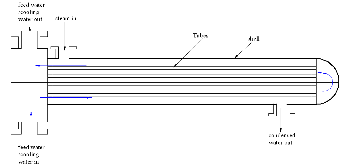
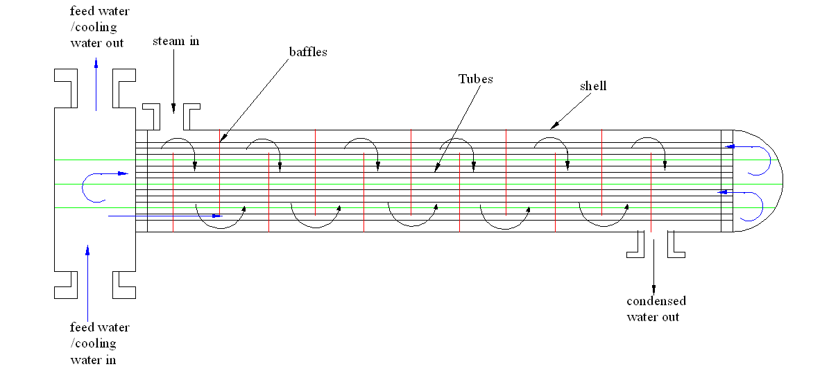
An explanation of the shell and tube heat exchanger
The shell and tube heat exchanger facilitates the movement of heat energy across two different liquids. In most cases, the coolant moves through several small tubes that run symmetrically within the exchanger while the steam runs within the shell. This results in the extraction of heat energy as the coolant or the feed water run on these small tubes. Figure 1 depicts the shell and tube heat exchanger.
Problem identification
In the Co-op session, the case study involved the heat exchanger system in order to discover some possible problems with it. The major challenge identified in this study was ineffective cooling. The rate of cooling was not satisfactory and the resultant water had high temperature. In addition, the system failed to achieve optimal condensation because some traces of steam escaped through the condensed water outlet. Hence, the heat exchanger did not perform optimally and was not sufficient. Further assessment of the system showed several challenges.
Inefficient flow of the dialysis water
Water flows into the tubes was not efficient. Water for distillation should flow at a constant pressure throughout the process. This ensures maximum absorption of heat energy from the steam and full condensation and cooling of the steam to the required temperature.
Poor flow of cooling water within the shell
The system did not maximize water flow within the shell. Cooling water flow should be as best as possible to ensure maximum removal of heat from the purified water.
The tube and shell components
The tube and shell parts hindered effective heat transfer between the coolant and the steam under distillation. As a result, heat transfer between the two fluids was not optimum.
Solutions to the problems
A number of approaches were developed to enhance the effectiveness of the heat exchanger. They included the following:
Improving the flow rate of the steam
Proper cooling requires an optimum flow of the steam. This ensures utmost transfer of heat energy to the coolant within the shell.
Maximizing the flow rate of the feed water within the shell
Coolant should also run at the most favorable rate to ensure efficient cooling and absorption of heat from the steam.
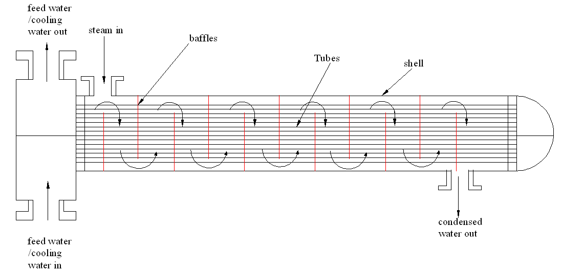
Enhancing the number of baffles
Several baffles would ensure that the steam goes through the system many times. This enhances cooling rate and effectiveness of the cooling process as shown in figure 2.
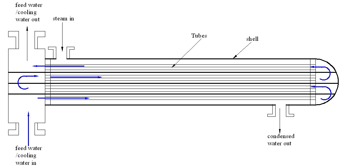
Adding many passes
Engineers could double the number of passes to facilitate optimal performance of the system. The installed heat exchanger has a double pass shell and tube. In such a setup, the coolant passes only twice in the tubes. Therefore, enhancing efficiency requires the coolant to pass through the system more than twice. This increases the effectiveness of the system and cooling process. Figure 3 captures the flow process of the coolant.
Increasing the number of baffles and the number of times by which coolant goes through the pipes
Increased baffles and the number of times the coolant passes through the heat exchanger enhance cooling efficiency. An increased number of baffles and frequencies of coolant passage will result in increased interaction between the coolant and the steam during distillation. Figure 4 shows the process of increasing baffles and frequencies of coolant passage.
Maintenance of the tubes
Usually, the tube’s surface is the main point of contact between the steam and the coolant involved in heat transfer. Therefore, a dirty coolant into the shell would deposit impurities and the surface and reduce its effectiveness. Any deposit of dirt on the surface of the tube results in poor conduction and transfer of heat, which affects the effectiveness of the cooling system. To this end, regular cleaning of the exchanger is necessary to remove dirty deposits. Corrosion may also occur because of oxidation on the sheet. Therefore, it is imperative to use chemicals to remove oxides.
Case Study 2: determining the tube thickness for heat transfer equipment
This case study involved determining the internal pressure and thickness of the shell. The internal diameter of the shell was 60 inches according to TEMA standard specifications. The maximum possible stress would vary from 17,000, 20,000 to 23,000 psi with joint efficiency that ranges from 0.7, 0.8 to 1.0. The aim was to determine the effect of these variables on the shell internal pressure and the required thickness. It also involved the evaluation of the effect on the circumferential and longitudinal strain.
Works Cited
Herzlinger, Regina. Consumer-driven health care: implications for providers, payers, and policymakers. San Francisco: Jossey-Bass, 2004. Print.
Hoffmann, Stephen. Planet water: investing in the world’s most valuable resource. Hoboken, N.J: Wiley, 2009. Print.
Jacobs, Claude. Replacement of renal function by dialysis. 4th ed. Dordrecht: Kluwer Academic, 2003. Print.